
Original prototype ca. '95
using PP OPTs hacked from a
Harman Kardon 500 integrated amp

!!!WARNING!!!
The voltages found in this circuit can be lethal, build at your own risk!!!


Mid 2004
The Simple 45/2A3 was literally taken out of the RCA tube R-C amp chart. Nonetheless, I firmly believe that its musical performance is hard to beat when driving suitable high efficiency speakers at around 90 dB/1W sensitivity or greater. My original concept for this project was to quickly whip out an SE amp using parts in my bin in order to evaluate the sonic merit of the type 45 DHTs I acquired at a hamfest in the mid 90s. Since my 2.5V filament supplies had enough current ability to light up 2A3s, I dropped them in place and heard decent sound thus sparing my stash of 45s for everyday use. I took it to Steve's shop one day and he was impressed by what he heard and asked me to write an article for the DIY section in his website.

Let's review the design topology of this circuit. It is a 2-stage resistance coupled amplifier using a 6SL7 - a hi-gain [mu], lo-transconductance [gm] dual triode as the input/driver tube capacitor coupled to the grid of either a 45 or 2A3 power triode operated in cathode bias. The input impedance of the amplifier is set by the 100K Radio Shack/ALPs volume control. It can be replaced by a 100K, 1/2-1W resistor if you don't need an input level control.

If you refer to the 6SL7 R-C amplifier chart, with a 300V supply, 100K plate load (Rp) and 2.7K cathode bias resistor (Rk) a single section of a 6SL7 is able to swing 63V to a grid load resistor (Rg) value of 470K. Since I had about 330V B+ supply to play with, by interpolation I can theoretically expect 10-15% greater voltage swing. However in real world applications this margin of voltage is wasted as heat [exacerbated by the lack of gm] dissipated by Rp when loaded by the input capacitance of the output tube and its grid resistor (Rg). Assuming that I have about 60 "real world" volts, this is still adequate to drive a 45 to full power since it is greater than the bias voltage [56V] of the output tube. To make sure that I maximized the amount of current drive, I decreased the cathode bias resistor to a 1K, bypassed with a 100uf/25V electrolytic to avoid degenerative feedback [more gain] or use a rechargeable 1.5V AA battery [see mods below].

According to the specifications for a type 45, operated as Class A single ended amplifier, with 275V (max.) at the plate and - 56V grid bias driving a 4600 ohm load [output transformer primary Z], output power is 2W. Each tube drawing around 35 ma. of current. Since I sonically prefer cathode bias over fixed bias, I needed a B+ supply of around 330V. When The Type 45 is operated in cathode bias, a grid leak resistor of no greater than 1M should be inserted from the input grid to ground, 470K fits the bill as recommended by the R-C chart. In a directly heated triode [DHT] like the type 45, the filament itself is the cathode. Cathode bias is achieved by inserting the proper value resistor either on the filament transformer center tap or at the center terminal of a hum bucking pot. Since AC filament hum can be a problem, I used 25-100 ohm, 2W hum bucking pot with 1.5K, 12W bias resistor bypassed by a 100uf/100V electrolytic cap [connected in parallel; watch for polarity "+" goes to the center tap] to the center tap of the pot. The filament supply calls for a pair of 2.5V @ 2.5A transformers like the easily obtainable Hammond 166L2. I get 2 mv. or less of residual hum from this arrangement.


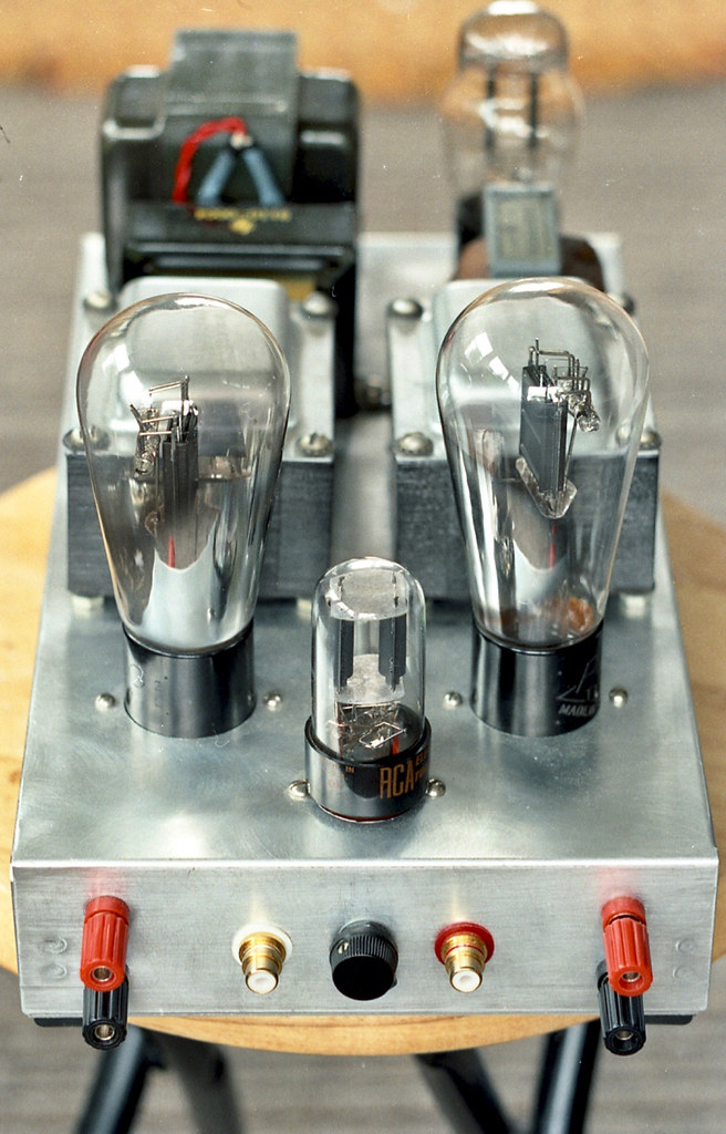
Mid 2004 with Hammond 125ESE OPTs
Even if this is a cheap design, I did not skimp on the power supply. I always believe that good sounding tube amplifiers and preamplifiers should be tube rectified with at least a choke along the initial stage of the B+ line. I used a 5Y3 tube rectifier in a pi filter topology [C-L-C] with a 10H, 150 ma. choke [L] between the first two stages of filter capacitors [C1] and C2] and then a split rail [R-C1 and R-C2] B+ line for the input/driver stage [6SL7] to minimize crosstalk between channels. The Hammond 272DX power transformer has a 600VCT HV winding @ 125 ma., 5V @ 3A and 6.3V @ 3A filament windings. This stereo circuit draws about 73ma. of current so there is a safety margin of 50 ma. from the HV winding. The 50 ohm, 10W resistor inserted between the rectifier and the first 10uf cap serves to fine tune the B+ supply so that the 45 output triodes will be well within its maximum allowable operating conditions. As a measure of safety, I always insert a 100K-250K, 2W metal oxide [see the PS section of the schematic] "bleeder resistor" to discharge the power supply caps while the amp is turned off. This will prevent electrical shock when the unit needs to be serviced since capacitors can store high voltages for a long time.

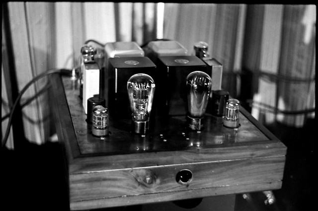
ca. 2005 with James 6113HS OPTs
Simple 45/2A3 FAQs:
1. Power transformer - you are on your own if you decide to use a power transformer other than specified in the above schematic.
2. Output transformers - the Hammond 125ESE output transformer sounds good and offer great value for the money. It is air-gapped and has multi tap secondaries - 2.5K, 5K and 10K - great for experimentation with other circuits or output tubes. No need to scavenge old tube receivers or integrated amps for high quality PP iron.
However for around $200/pair, one can get significant improvement in overall transparency, resolution, dynamics and bass response with the James 6113HS or better yet the 6115HS available at eBay.This unit uses higher grade M3 laminations potted in a cylindrical can with Tango ISO/Tamura level of finish. This output transformer really excels and have used it 2A3 applications at over 60 ma. current and was not put to shame pitted against the more expensive and beefier Tango U808 and NY15s. This is an unequivocal best buy in my book because of its synergy with this circuit!
For those with even bigger budgets, I've also had success with this circuit using the Tamura F475, Tango U708 [discontinued], H-5S [discontinued], Tango ISO U808 & Magnequest TFA204 [3k, 2A3s, use the 4 ohm tap to reflect a 6k primary Z for 45s]. Perhaps the added expense may not be justified in this simple application, but I'd leave that to the ears of the beholder...
3. Miller Effect - I have been warned in the past by more experienced DIYers as well as criticized by techies who think the 6SL7 is not the ideal input/driver tube due to its low transconductance being inadequate to drive the high capacitance of a directly heated triode's grid. Perhaps my naivete and empirical approach to DIY paid off because the anemic driver stage assures pure Class A1 operation and enhances the already well know virtue of soft clipping and even order distortion harmonics inherent in tube devices.

Ding's Simple 45 ca. '96
4. Mods - the only modification I did to this circuit is batter bias. Remove the resistor/cap combo at the cathodes of the 6SL7 and replace with a rechargeable 1.5V AA Ni-Cad or NimH battery like I did on the JEL phono stage schematic. Positive side of the battery to the cathode and negative to ground. To my ears this adds definition and clarity which may be system or taste dependent.
5. Parts - I always use carbon composition or carbon film resistors for plate load, metal oxides in the power supply, paper in oil coupling caps, Sprague Atom electrolytics for power supply decoupling and cathode bypass. It is a very simple circuit, season to taste ;)
6. Primary Z of OPT - some people have expressed concern on the use of 5K load for a 2A3 which only requires 2.5K according to the tube manual. Well folks, as stated the operating point for this amp is for a type 45 and since this is not the most linear region for a 2A3 a higher impedance load reduces distortion and improves damping factor in the low frequencies. I've measured 2.5W output from this circuit with 2A3s inserted, it sounds more dynamic and punchy lacking only the purity and refinement of a type 45.
7. Plate vs. B+ voltage - Steve at Angela Instruments and I have received several inquiries as to why the type 45 is being taxed over its limit. That is because many people get confused between plate voltage and B+ voltage. Here are some equations to calculate for plate voltage, plate current and plate dissipation (Ohm's law) which will clarify the matter (DC voltages as per schematic):
- B+ voltage [325V] - cathode voltage [55V] = plate voltage [270V]
- cathode voltage [55V]/cathode resistor [1500 ohms] = plate current [.036 or 36ma.]
- Plate voltage [270V] x plate current [36ma. or .036] = Plate dissipation [9.72W]
As you can see the type 45 DHT is operated well within the recommendations of the tube manual.
Through the years I have received numerous emails from builders of the Simple 45/2A3 praising its musical virtues. It is an amp that appeals more to a hobbyist who listens more to the music than equipment.
During the November 2011 Hi-Fi Show my cohorts and I featured this not so simple 45 behemoth of an amp (weighed over 60 lbs.) built by Joel Villanueva. It is a dual mono block on a Harana Audio chassis made from a 6 mm thick copper plate bolted on a Philippine Mahogany base using 300% over rated power transformers, low DCR chokes, Hashimoto OPTs, silver wires in the signal path, Allen Bradley resistors and paper in oil caps driving 100dB efficient JBL horn speakers!
The first watt rules!
Hello Mr. Esmilla! I've been one of your strongest fans since the beginnings of this century and I've built your SET300B with very good results: it gave me hours and hours of great listening pleasure! Now I'd like to build a 45 SET amplifier, since I love this tube, for my new setup and this clean and simple design is one of my favourites. I saw in your photograph of the James output tranformers version that you chosed a single triode in the input stage insead of half a 6SL7. Is it a 6SF5? or another hig mu triode? Thanks in advance and buona Musica from Vincenzo (Milan, IT).
ReplyDeleteHi Vicenzo,
DeleteThanks for the kind words! Yes it was a 6SF5. Good luck and happy listening!
JE
Thank you Joseph! Enjoy Music, enjoy Life!
ReplyDeleteMate, thanks for such an informative article\post. You have explained all very well and though I'm an experienced builder it is helpful. Let you know if I build one.
ReplyDeleteThanks once more.
http://retro-thermionic.blogspot.com.au
Hello, I was looking to build the simple 45. I started getting into tube amps about 2 years ago and haven't looked back. After acquiring a simple 2A3 from Handmade Electronics. I think triodes are wonderful. I have a question about the rheostat value? also that is a 1.k 12 watt wire wound resistor going to the wiper?
ReplyDeleteI hope my adventure turns out sounding good.
Thanks
Jose
Anywhere from 25 ohm to 75 ohm @ 2W minimum potentiometer should work + 1.5k, 12W minimum for cathode bias.
DeleteHappy soldering and listening!
JE
Hello,
DeleteI finally finished the amp, and sound pretty good, one of the channels has no sound. I measured the voltage at pin 5 of the 6SL7 and its 290 Volts when it should be 149 Volts. Can this be a bad coupling cap?
I doubt it's a coupling cap issue. Assuming your 6SL7 is good, the plate is not drawing current = no sound! Check the corresponding cathode voltage, look for cold solder joints and mis-wiring. It's a very simple circuit, you should be able to trace it using the working channel as a model.
DeleteHappy sleuthing!
Wow so I put some extra solder on pins 4,5,6. Seems it was a cold solder. Sounds amazing. Thanks so much. Any phono preamp projects?
DeleteGood to hear that!
DeleteI built this last summer -http://jelabs.blogspot.com/2017/12/jel-loctal-preamp.html - sounds good but not necessarily better than the RCA derived phono, just different.
Hello Again,
DeleteMy father in law wants one, but he is Japan, how do I wire the circuit since AC voltage is non-polarized with no ground? The circuit makes sense to me for US with ground. Will the DC portion be floating?
Thanks
Jose
The AC will be wired just like anywhere in the world. What you need for use in Japan is a power transformer with a 100V primary. Or you can use a US 120V transformer and use a 100>120V transformer in Japan.
DeleteJE
Wow this is an incredible looking amp circuit! Ive looked at so many circuits for the 2A3 my heads going to explode. I have a few tube amps under my wing for guitar but only one HIFI tube build and this looks like the one I'll build. Have there been any other changes? My real question was how come you didnt heat the 2A3's with DC? I see alot of these amps with DC heaters
ReplyDeleteI haven't made any changes to this particular circuit. But last year I built a variant of this circuit using a Type 46 power tube - http://jelabs.blogspot.com/2017/10/je-labs-simple-46.html
DeleteIf properly wired the AC filament residual hum on this amp can be nulled down to 3mV. To my ears that is soft enough even with my 99dB/1M/1W efficient Altec 2-way.
JE
Appreciate such a good simple project, and like your voice saying that "listen more to the music than equipment".Yes, enjoy music.
ReplyDeleteI read the circuit, the decoupling B+ 331V of 6SL7 that is 1V higher than 45's B+, after a 2.7K resistor. Have I overlooked something in the circuit? Would you comment?
Thank you,
Leed
Disregard the 331V, I will edit it out. That schematic works. I used it as basis for the Simple 46 I built a year ago.
DeleteThanks for notice!
JE
JE, thanks for this amplifier design and publication. It sounds very good and is being enjoyed tremendously by me and everyone who listens to it.
ReplyDeleteAs I am ignorant to a lot about this hobby. I have a mild thump in the speakers upon startup and wondering if this is normal. I checked all solder joints and distance between wiring terminations are all at a reasonable distance. Any comments or suggestions would be appreciated.
Again thanks.
Doug
Hi Doug,
ReplyDeleteI wouldn't worry too much about a mild thump. That's quite normal with tube amplifiers. I'm glad you're enjoying the amp!
Cheers!
JE
JE, i thank you for your design and sharing it with the hobbiest. I've built the je labs simple 45 and it sounds fantastic paired with tannoys HPD315. I used Audionote non magnetic resistors, Mundorf tubcap for the psu stage, mills cathode bias resistors with f&t caps, tkd 2cp 2500 gain controls, edcor GXSE 5k output transformers. I am really happy with the overall sound of this amplifier, i know for certain with better output tranny i can gain a broader margin of better sound, this is my first tube amplifier build and been listening to it for about 4 months now with RCA 45 tubes and they are doing a great job. To my ears its what music is supposed to sound like. I have ordered a pair of EH 2a3 tubes coming soon, cant wait to hear what it would sound like. Thanks again.
ReplyDeleteBest regards.
I recently dusted off my Simple 45 amp with Tamura F475s. This chassis went through several driver circuits from Simple, SRPP, 76/6SN7, etc. It's been back to its Simple configuration for several years.
DeleteStay safe and happy listening!
JE
JE,
ReplyDeleteHi Hope all is well on your end. Thank you for you sharing your design with the Hammond 125ESE. I do have a pretty basic question. If I'm using the amp with an old 16 ohm Jensen speakers, how should I wire the 125 ESE? Do I use the white or yellow wire on the 125ESE? If I want to use it on a 4 ohm speaker do I use the orange wire? Thank you
Elton
I don't have the color coding of the 125ESE from memory and that's over 20 years ago. So I had to refer back here -https://jelabsarch.blogspot.com/2012/07/hammond-125ese-part-1.html - wire it to reflect a 5K (5000 ohm) load to the primary. So if you are using 16 ohm Jensens, the secondary = black (0) and white (16), and so fort...
DeleteJE
JE,
DeleteThank you for your help. Stay safe.
Elton
Hi, thanks for sharing and building it first timer. I wonder if the input signal ground joins the 1K and the 100uf to ground at that 3 way junction? Just want to make sure in case it's a fly over from the 1K to ground that sort...
ReplyDeleteCheers
Man
Yes, they are connected at the same ground point. Those scans came from my defunct website and are over 20 years old.
DeleteSorry another question: the Hammond 272dx spec seems to specify a secondary of 600v, while the circuit diagram is with Red (300) on the top and Red (200) on the bottom with CT to the gnd?
ReplyDeleteI am looking for an 230v alternative so checking out the 372DX with similar spec to the 272DX but with universal primary. So a 600V secondary? Cheers
They should both read 300. If the 372dx is the equivalent with 120/240 primaries, then you are good to go.
DeleteHi JE,
ReplyDeleteI am using Simple 2A3 for last 2 years with Hammond 125ESE. It is sounding great and i have paired the same with Altec 414/804A combination in 614 box.. Recently i got hold of Hashimoto HC203U for 300B project which may kick of in 2021.. Do you suggest whether there will be phenomenal improvement if i change the Hammond tran.to HC203U in place of Hammond 125ESE in simple 2A3 ?
Congrats on the HC203U, nice iron!
DeleteI started this DIY audio blog to encourage self discovery among audio hobbyists because as humans, our perception of music and sound vary greatly. Here's my advice - install the HC203Us in your present amp and listen to all the types of music you love for at least a week or more.
Then ask yourself, do I need the extra couple of watts of power? Can you justify the extra expense and complexity of building a 300B amp?
As stated in the last sentence above, the first watt rules!
Thanks JE, fantastic advice.. Have less courage to have self discovery and have to depend on others to assemble fully, still i am in learning curve in DIY.. Following your ideas and for sure it is satisfying the music soul to great extent... So taking one step forward by taking your advice, since you had played around with lot of iron in your 2A3 build.
ReplyDeleteHi I'm Mordjen from Besançon , France.
ReplyDeleteSo, many years ago, I builded my 2a3 SE JE LABS 2001 edition.
Now I m looking for his schematic cause i'have lost it.
At first the schematic was available on angela.com page, but actually it is removed.
Please, could you help me finding it.
Thanks a lot
I moved a couple of times in the past 20 years and lost my copy, sorry!
DeleteBTW, I replied to your post in Audiokarma.
Hi there,
ReplyDeleteI am considering this as my first point-to-point (and without an exact part list) amp project, however I also care for the sound quality so I am researching for good quality transformers at humane prices.
I came across One Electron products: http://www.one-electron.com/Products/trans.html Looking at the spec sheet for the UBT2 OPT, it has a 4.8 K impedance and lists the 45 in its test sheet. Your diagram with the 125ESE has 5.0 K. Would that make a difference?
Also, could I use their power transformer for this project? http://www.one-electron.com/Products/Trans/BFT1B_11.pdf
I apologize for any naive questions. Thanks.
For all intents and purpose, 4.8K = 5K.
DeleteI haven't had ears/hands-on experience with any of the UBT products but AFAIK, they've been around since the early 90s which in itself, indicates reliable products at the very least.
It looks like the 520VCT winding of the BFT1B power transformer will work in this project. But don't be surprised if the voltages aren't exactly as in the schematic - 5-10% was the accepted norm in the tube era.
Happy building and listening!
Thanks for the advice. While I'm looking at the same brand, would you say that their PRC-2 choke (12H / 150mA vs. your schematics at 10H 150mA) work as well?
DeleteThanks again,
gm
Yes to PRC-2 choke!
DeleteThanks again! I may have other questions but I'll ask them in DIYAudio so I don't clutter your forum...
Deletegm
Hello,
ReplyDeleteI'm in the process of building the 2001 version of this amp, which uses the GZ37 as rectifier. The schematic is from Angela (http://web.archive.org/web/20060618122016/http://www.angela.com/catalog/how-to/SE.2A3.html)
It occured to me that according to the GZ37 specs the first cap after the tube should not exceed 4uF, yet in the schematic it's 20uF. Is there a specific reason for this? or more specific: would the 20uF work for the GZ37?
Thanks in advance,
Mick
I may have misread the data sheet. In fact, I'm still using the same pair of GZ37s on my SE300B mono blocks with 47uf at the input. Since these tubes are very expensive and hard to come by nowadays, I suggest you follow the 4uf spec. Just make sure you have at least a 10H choke after the 4uf and another 100uf on the other side of the choke.
DeleteHave fun and happy listening!
Somehow I missed your reply. But thanks for the info!
DeleteHi JE,
ReplyDeleteI just wanted to let you know that I've just completed a 45 build using a version of your schematic and wanted to pass along my gratitude.
I've used Hashimoto OPTs, black gates and audio-note capacitors on the cathodes, Vitamine Q and Jensen as DC blocking caps and a stepped ladder attanuator, and although originally intended as headphone amp for the office, it's now replaced my amp in the main set, so impressed I am with the sound (despite the relatively low efficiency of my speakers).
Unfortunately, I can't seem to place pictures here but opted for a more modern look for this classic circuit! Again thanks!
Matthew
ps. your NOS DAC is my next project :)
I'm glad that you're enjoying your Simple 45 amp! I've tried several circuits to drive the 45 triode but always went back to this circuit.
DeleteSend me another message with your email address. I won't publish it, instead I'll reply directly so you can send me pictures of your project.
Thanks!
JE, I’ve been a fan of your tube amp designs for a while now. I really appreciate all of the hours of enjoyment that you’ve provided in guiding me in this hobby. I’ve built your 76/6SN7 line stage and love it. After that I was looking for a 2A3 amp schematic and came across your Simple 45 / 2A3. I finished it last night. Very nice! I couldn’t find any of the recommended output transformers, so I used a pair of Edcor Gxse15-5k-8-15w. I have nothing to compare them to, but so far, they sound very good. The only snag that I’ve run into is that all of the operating voltages are slightly lower than specified in your schematic when my line voltage was 120.0 vac. I didn’t have a 2 amp fuse, so I used a 1.5A. My guess is that smaller fuse is acting like a current limiter and slightly lowering the voltages. I’ll swap it out as soon as I find one. I have photos of my build and if you’d like them, I’d be very happy to share. Thanks again. Jeff
ReplyDeleteI'm glad you're enjoying the sound. I just want to clarify that although the 2A3 will work and play nice tunes, the amp was really designed for the type 45 triode.
DeleteAs long as you're within 10% of the voltages listed, I wouldn't worry too much. Besides, the fuse rating won't have any effect. It's wired in the primary winding of the transformer so that if a tube shorts or a capacitor fails the fuse blows and save the rest of the amp.
Happy listening!
Hi JE, when you used the Tango H-5S output transformers with the 45 or 2A3 did you find the low frequency rolled off?
ReplyDeleteI haven't found specs but I'm thinking of buying a pair to try.
Thx
The quick answer is no. In fact I still use the H-5S OPTs in my SE171A amp - https://jelabs.blogspot.com/2024/02/se171a-amp-remastered.html
DeleteOf course, a high quality 20W SE Tango OPT will present more authoritative bass response. There's just no way around the laws of physics. The sonic difference is akin to using a DL103 in a 12" vs. 9" tonearm. You might also get better bass response from PP or para-feed but you'll lose the SE midrange magic. Everything in audio is a compromise.
Remember, the Japanese rediscovered the SE topology in the late 60s/early 70s when they started importing "unloved" WE91A SE amps. Then in the mid 70s, Jean Hiraga wrote about them in L'Audiophile. The English speaking world had to wait another two decades until Joe Roberts started publishing Sound Practices in the early 90s. That was the only time North America retooled for SE OPT manufacturing.
Thanks JE
DeleteBTW, get the H-5S only IF they're significantly cheaper than a brand new pair of equivalent Hashimotos. For ex: the HC507 will have better bass response with slightly less transparent mids because those use EI lams instead of C-core in the H-5S or the H507S.
DeleteThe Japanese yen is very weak right now. If you email Mr. Asakura in Michigan -http://www.tube-amps.net/Hashimoto_Products.htm - you might be surprised at the discount from his website prices.
Good luck!
Thanks, will do.
DeleteMy speakers -3db point is 50hz, so I'm thinking the H-5S will be fine hopefully.
I've always wanted to try a classic Tango as well.
I've used most others but never tried a Tango or Tamura.
Looking forward to it.
👍😊
DeleteHi JE, I was curious if you tried the 45 cathode resistor un-bypassed? What would be the possible negative to this and can you use a smaller value cap if required? Such as a film cap.
DeleteIf the -3db point is an issue, do you calculate this with just the cathode resistor value or do you add the tubes Ra as well?
Years ago I forgot to install the bypass cap = much less gain and sounded lifeless.
DeleteYou can experiment using Mylar/PIO/PP/PS, etc. caps of different µf value but appropriate voltage rating and decide what sounds best.
Good to know, I won't bother even trying it then.
DeleteThanks very much for sharing all this great information with the diy community, it is much appreciated. I've built quite a few amps over the years and the simple 45 is still my favorite.
The circuit is as you have it, but I played around a bit with power supply configurations and ended up preferring a choke input supply.
So musical, it holds up in a multi buck system and sounds great with a wiim streamer and a $200 pair of bookshelves!
I'm still tempted to try the srpp version just because it's fun and it's what we like to do.
Btw, really enjoy your sound clips and system videos on YouTube.
Thanks again.
As I've said above, I tried quite a few ways of driving the 45 DHT but always gravitated back to this circuit. I'm glad you're enjoying music through this amp!
DeleteThanks for the kind words about the blog and my youtube channel!
Can you use a 10h choke @ 125 ma?
ReplyDeleteYes!
DeleteIs there any modifications required to the schematics if you build this as mono blocks? Aside from 2 power supplies with 1 filament transformer each.
ReplyDeleteI know people who've built mono block versions of this circuit but they figured out on their own what parts to buy to maintain the operating voltages shown in the schematic.
DeleteI can't really help beyond what I already provided above because what you're asking for involves a major redesign. Besides, my formal training is in classical music, not electronic engineering.
Ok thanks!
Delete